What Is Injection Mold Manufacturing and How Does It Work?

Injection mold manufacturing is the process of creating precision tools that shape molten plastic into repeatable products. These tools support industries such as medical devices, automotive parts, electronics, and consumer packaging. A mold may look like a simple metal block. It is not.

Inside, carefully machined cavities define the product’s geometry. Engineers also design runners, gates, cooling channels, and ejection systems. Each feature affects filling speed, surface finish, cycle time, and product consistency. During production, a molding machine clamps the tool under high pressure. Plastic pellets melt inside a heated barrel. The machine then injects the material into the cavity. Cooling follows. The solidified part is ejected, inspected, and prepared for the next cycle.

Good injection mold manufacturing depends on more than accurate machining. It requires practical experience, reliable material data, and disciplined process validation. Engineers review wall thickness, draft angles, shrinkage, and possible weld lines before cutting steel. Skilled technicians then polish surfaces, fit moving components, and test the mold under real operating conditions. Small details matter. A blocked cooling channel can lengthen every cycle. A poorly placed gate can leave visible marks.

The process is highly repeatable, but never completely effortless. Material batches can vary slightly, and real machines rarely behave like simulations. That gap deserves attention. Careful sampling, dimensional checks, and documented adjustments help manufacturers control risk. When design, tooling, molding, and inspection work together, injection mold manufacturing becomes a dependable path from digital concept to physical product.
What Is Injection Mold Manufacturing and How Does It Work?

What Is Injection Mold Manufacturing?

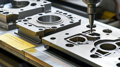
Injection mold manufacturing is the engineering process of creating a reusable tool for producing plastic parts. It starts with steel. Engineers convert a digital part design into mold halves, cavities, cores, runners, cooling channels, and ejector systems. Machining removes most material, while electrical discharge machining forms deep or sharp features. Surface polishing then improves appearance and release performance.

During molding, thermoplastic pellets are heated and injected under pressure into the closed cavity. The material fills each feature, receives additional packing pressure, and cools against the mold walls. Ejector pins then remove the finished part. Temperature, pressure, cooling time, and shrinkage must work together.

A 2024 market report from Grand View Research estimated the global injection-molded plastics market at about 387.1 billion US dollars in 2023. That scale reflects the process’s importance in automotive, medical, electronics, and household production.

Precision does not guarantee perfection. Small errors multiply. Uneven cooling can create warpage, sink marks, or visible weld lines. A moldmaker may run several trial shots, measure critical dimensions, and adjust gates or cooling channels.

Industry tooling practice often targets repeatable dimensions, yet the practical tolerance depends on resin, geometry, mold steel, and part size.

One detail is easy to underestimate: maintenance. Vents can collect residue, and worn ejector pins can change part appearance. Careful inspection remains necessary, even when the mold appears mechanically sound.

Key Components and Materials Used in Injection Molds

Injection mold manufacturing begins with a tool that shapes molten plastic under controlled pressure. A typical mold has two halves: the cavity side forms the outer surface, while the core side creates internal features. Together, they close around the parting line and open after cooling. The sprue, runners, and gates guide material from the machine nozzle into each cavity. Ejector pins then push the cooled part out without damaging critical surfaces. Experienced mold makers inspect these paths closely because small restrictions can create burns, short shots, or uneven filling.

Tool steel is common for high-volume molds because it resists wear and holds precise dimensions. Pre-hardened steel can reduce machining time and suit moderate production demands. Aluminum molds cut lead time and weight, but they usually wear faster.

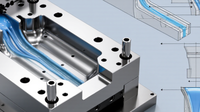
Inside the mold, cooling channels remove heat through circulating water. Their layout affects cycle time, shrinkage, and surface quality. Copper alloys may improve heat transfer near difficult areas, although they need careful placement.

The choice is never just about material price. Maintenance, production volume, resin type, and expected tolerances matter equally.

The molded part also depends on resin behavior. Nylon, polypropylene, and engineering plastics flow, cool, and shrink differently. Draft angles help release parts cleanly, while vents let trapped air escape.

A practical review checks wall thickness, gate location, weld lines, and ejection marks before cutting steel. Even careful designs can miss a thin rib or an uneven cooling zone.

That mistake is expensive. Trial molding reveals these weaknesses through measurements, visual inspection, and repeated adjustments. Mold manufacturing is therefore a balance between geometry, heat control, durability, and realistic production conditions.

How Injection Mold Design and Engineering Are Completed

Injection mold design begins with the part, not the machine. Engineers review wall thickness, draft angles, ribs, bosses, and likely shrinkage. A 2024 market analysis estimated the global injection-molded plastics market at over 200 billion US dollars. That scale rewards disciplined engineering, but it also exposes weak designs quickly.

The team then builds a 3D mold model and checks parting lines, gate locations, cooling channels, ejector pins, and steel strength. Flow simulation can predict filling pressure, weld lines, air traps, and warpage. It is useful, not magical. Shop-floor temperatures and material batches can still change the result. Mold trials reveal those gaps. Engineers measure dimensions, inspect cosmetic defects, and adjust steel carefully. Cutting metal too early remains an expensive mistake.

Tips: Keep walls as uniform as possible. Use draft on every molded surface. Place gates near thicker sections, but verify the appearance requirements. Plan cooling before detailing the ejector system. According to PlasticsEurope’s Plastics—The Fast Facts 2023, global plastics production reached 400.3 million tonnes in 2022. That figure reinforces one practical point: material selection and recovery planning belong in design discussions, not after production starts. I would also challenge one common assumption: the fastest cycle is not always the best cycle. Excessive cooling reduction may increase warpage, scrap, and maintenance. Good engineering balances cycle time, repeatability, tool life, and the operator’s real experience.

What Is Injection Mold Manufacturing and How Does It Work? - How Injection Mold Design and Engineering Are Completed

Engineering Stage Main Activities Typical Design Data Manufacturing Output Key Quality Controls Typical Timing or Range
1. Product Definition Review the part function, appearance requirements, assembly method, expected production volume, and material selection. Part dimensions, wall thickness, draft requirements, shrinkage value, surface finish, and tolerance targets. Approved product specification and design-for-manufacturing requirements. Material compatibility, functional tolerances, cosmetic zones, and assembly clearances. Completed before detailed mold design.
2. Mold Concept Design Select the mold type, parting line, cavity arrangement, runner layout, gate location, and ejection strategy. Single-cavity or multi-cavity layout, mold orientation, projected area, runner balance, and available machine capacity. Preliminary 3D mold layout and manufacturability review. Balanced filling, safe part release, reasonable cycle time, and sufficient mold strength. Commonly evaluated before detailed tooling drawings.
3. Moldflow and Filling Analysis Simulate melt flow, filling, packing, cooling, weld-line formation, air traps, and shrinkage behavior. Melt temperature, mold temperature, injection speed, packing pressure, cooling time, and material data. Recommended gate, vent, cooling, and process-control locations. Predicted filling balance, warpage risk, air evacuation, and dimensional stability. Used when geometry, material, or tolerance risk is significant.
4. Detailed Mold Engineering Create complete mold drawings and 3D assemblies, including core, cavity, sliders, lifters, ejectors, cooling, and mold base. Steel selection, component dimensions, cooling-channel diameter, ejection stroke, and standard component specifications. Released manufacturing drawings, bills of materials, and inspection points. Interference checks, steel safety, venting, alignment, maintenance access, and assembly sequence. Completed before steel cutting and machining.
5. Material and Steel Preparation Prepare mold steel, electrodes, inserts, plates, guide components, cooling fittings, and auxiliary tooling. Steel hardness, corrosion resistance, thermal conductivity, wear resistance, and required surface treatment. Verified raw material, rough-machined blocks, and traceable component records. Material certificates, hardness checks, dimensional allowance, and identification control. Steel grade depends on volume, resin abrasiveness, and surface requirements.
6. CNC, EDM, and Precision Machining Machine mold plates, cavities, cores, inserts, runners, and complex features using CNC milling, turning, drilling, and EDM. Machining tolerances, electrode offsets, datum structure, surface-finish targets, and heat-treatment allowances. Precision-machined mold components ready for fitting and finishing. Coordinate measurement, tool wear monitoring, electrode verification, and surface inspection. Fine features may require multiple machining and finishing operations.
7. Heat Treatment and Surface Finishing Apply heat treatment when required, then polish, texture, coat, or finish cavity and core surfaces. Target hardness, polishing grade, texture specification, coating requirement, and dimensional compensation. Finished cavity surfaces and wear-resistant working components. Hardness, surface roughness, visual uniformity, edge condition, and post-treatment dimensions. Surface finish is selected according to appearance and release needs.
8. Mold Assembly and Fitting Assemble mold components, fit parting surfaces, install cooling lines, connect ejection systems, and verify moving mechanisms. Alignment clearances, shutoff conditions, ejector travel, slider movement, cooling-circuit layout, and fastening torque. Mechanically complete mold ready for machine installation. Smooth opening and closing, no interference, reliable ejection, and leak-free cooling circuits. Assembly follows the released mold structure and inspection plan.
9. Mold Trial and Process Setup Install the mold on an injection machine and adjust filling, packing, cooling, ejection, and material-drying conditions. Clamping force, shot size, injection pressure, injection speed, melt temperature, mold temperature, and cycle time. Trial parts, process records, defect analysis, and corrective-action list. Short shots, flash, sink marks, warpage, burn marks, weld lines, and dimensional variation. Cycle time often ranges from seconds to several minutes, depending on part size and wall thickness.
10. Validation and Final Approval Measure sample parts, confirm appearance and function, verify repeatability, and document approved process conditions. Critical dimensions, geometric tolerances, weight, visual standards, assembly performance, and capability results. Approved mold, inspection report, process window, maintenance instructions, and production release. Dimensional inspection, functional testing, repeatability checks, and documented acceptance criteria. Approval is required before regular production begins.
11. Production and Maintenance Run the approved process, monitor part quality, clean the mold, lubricate moving components, and replace worn parts when necessary. Production quantity, cycle count, inspection frequency, preventive-maintenance interval, and spare-component list. Consistent molded parts and maintenance records supporting mold service life. Process stability, cavity balance, cooling performance, flash control, and wear monitoring. Maintenance frequency depends on resin type, mold complexity, cycle count, and production environment.

Step-by-Step Injection Molding Manufacturing Process

Injection mold manufacturing turns heated polymer pellets into repeatable parts. The workflow starts with product design, material selection, and mold engineering. Engineers check wall thickness, draft angles, shrinkage, and likely weld lines before cutting steel or aluminum. These details affect cost and quality. A 2024 global market assessment estimated injection molding revenue at more than USD 280 billion, showing the process’s industrial importance.

The machine then dries the pellets and feeds them into a heated barrel. A rotating screw melts and mixes the material. The screw pushes the melt through a nozzle into a closed mold. Pressure holds the material against the cavity walls while cooling channels remove heat. The mold opens, and ejector pins release the finished part. Cycle time often depends on cooling, not filling. Small errors multiply.

Technicians inspect dimensions, surface marks, weight, and short shots after trial runs. They may adjust temperature, injection speed, holding pressure, or cooling time. Data from the U.S. Department of Energy identifies injection molding as an energy-intensive plastics process, so efficient heating and shorter cycles matter. The method is highly repeatable, but it is not automatically perfect. Warpage can still appear after an apparently successful run. I have found that mold venting and uneven cooling deserve more attention than many early designs receive. A sensible process records every setting, sample result, and corrective change. Industry quality reports commonly emphasize this traceability because undocumented adjustments are difficult to reproduce.

Quality Control, Applications, and Mold Maintenance

Injection mold manufacturing creates repeated plastic parts by forcing molten resin into a machined cavity. The mold then cools, opens, and ejects the component. Cycle time depends on resin, wall thickness, cooling channels, and machine settings. A tiny temperature drift can change shrinkage, gloss, or dimensional accuracy.

Quality control begins before production. Technicians verify steel hardness, cavity dimensions, resin certificates, and mold alignment. During molding, sensors track pressure, temperature, and cycle time. Parts are checked with gauges, vision systems, and coordinate-measuring equipment. PlasticsEurope reported global plastics production of 400.3 million tonnes in 2022, showing the scale behind this discipline. Yet volume does not guarantee quality. One overlooked vent can create burn marks across thousands of parts.

Applications range from medical housings and electrical connectors to automotive clips, food containers, and consumer components. Each use requires different tolerances, surface finishes, and material controls. The 2023 Smart Manufacturing and Operations Survey reported that 86% of manufacturers viewed smart production as a major competitiveness factor. In molding, that means using process data, not relying only on operator judgment.

Mold maintenance protects both accuracy and uptime. After scheduled runs, teams should clean vents, inspect ejector pins, lubricate moving surfaces, and check cooling circuits for scale. Preventive records should include cycle counts and recurring defects. Maintenance intervals are not universal. They depend on resin additives, production volume, and mold design. I have seen “minor” flash ignored until it damaged the parting line. That mistake is expensive. Regular inspection remains imperfect, but it exposes problems earlier.

What Is Injection Mold Manufacturing and How Does It Work?

Injection molding uses a metal mold to shape molten thermoplastic material under pressure. A typical production cycle includes mold closing, injection, packing, cooling, and ejection. Cooling commonly takes the largest share of the cycle because the molded part must become rigid enough for safe removal.

The chart shows a representative 16-second cycle for a thermoplastic injection-molding process. Actual times vary with resin type, wall thickness, part geometry, mold temperature, machine settings, and cooling-system design. Quality control typically verifies dimensions, appearance, weight, and process stability, while preventive mold maintenance focuses on cleaning, lubrication, vent inspection, and wear monitoring.

NEW JERSEY

Location

Union Tool & Mold is a mold making, repair and plastic injection molding company located in central New Jersey.
(973) 763-6611

220 Rutgers St, Maplewood, NJ 07040
ACCREDITED

Certified Company


SOCIAL PROFILE

Let’s Connect

We invite you to engage with us on LinkedIn, where you can stay updated on our latest news, insights, and professional opportunities.