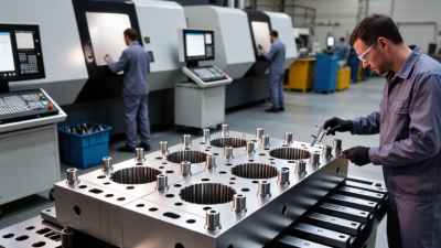
What are the top injection mold design tips? The best answers begin with the part, not the machine. John Beaumont, an injection molding specialist and co-author of Successful Injection Molding, is often associated with this practical reminder: “The mold is the heart of the process.” Treat that as a design principle, not a substitute for testing. A reliable injection mold design considers resin behavior, part geometry, tooling limits, and the production conditions the mold must withstand.
Start with uniform wall thickness. A sudden change from a thin panel to a thick boss can create sink marks, uneven cooling, or distortion. Add generous radii to corners, and use draft so parts release without scuffing. Place gates where material can fill the cavity steadily; a poor location may leave weld lines across a visible surface. Check ribs, bosses, vents, and ejector-pin positions together. They compete for space. They also affect strength, filling, and release.
Small details matter. A sharp inside corner can concentrate stress. A blocked vent can trap air near the end of fill. Before steel is cut, review the part with the molder and resin supplier, then use flow analysis where it can answer a real question. Still, simulation is not a promise. Tool trials may reveal issues the model missed. That is an uncomfortable truth, but a useful one. The tips ahead focus on choices that reduce avoidable rework while leaving room for evidence from actual molding trials.
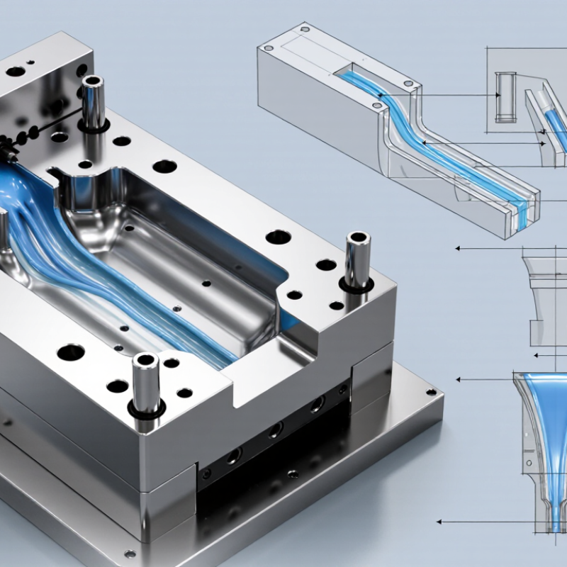
Before CAD begins, define the part’s function, annual volume, target cost, resin, and acceptable defects. These decisions shape cavity count, gate placement, cooling, press size, and tool life. A thin enclosure made for hundreds of thousands of cycles needs a different tool strategy from a short-run component. Set tolerances only on critical features, such as a snap-fit or sealing face. Do not guess.
Specify the resin grade, color, recycled-content target, and operating environment. Include shrinkage, chemical exposure, and temperature requirements in the design brief. The OECD’s 2022 Global Plastics Outlook estimated that 460 million tonnes of plastics were produced worldwide in 2019, while only 9% of plastic waste was recycled. That figure makes end-of-life planning relevant before steel is cut. If recycled resin is required, confirm its grade and consistency early; material variation can affect dimensions and appearance.
Provide the mold designer with 3D geometry, critical 2D dimensions, cosmetic zones, and expected cycle time. Identify permitted parting-line marks and likely weld-line locations. Confirm the target press’s shot capacity, clamp force, platen size, and tie-bar spacing. I would question any schedule that approves the mold layout before resin and machine constraints are fixed. It may look faster, but late changes can mean costly rework.
In production reviews, I have seen material choices reshape a mold before steel is cut. Glass-filled polymers may demand stronger tooling because abrasive fibers wear gates and runners. They also shrink differently along and across the flow direction. That matters. Use the supplier’s shrinkage data, but verify it with flow analysis and trial parts. Published values are useful, not absolute.
Part geometry sets the mold’s daily workload. Uniform walls usually fill more evenly and reduce sink marks near ribs or bosses. A practical wall transition should be gradual, not a sudden step. Draft angles help parts release without scuffing polished surfaces. Deep pockets, sharp internal corners, and trapped air need special attention. Add radii where stress gathers. Do not hide thin sections behind cosmetic requirements; they can freeze early and create weak weld lines.
Cooling design must follow both material behavior and geometry. A thick boss can stay hot while the outer wall feels solid. Without balanced cooling, warpage may appear hours after ejection. One early design I approved was too optimistic about cooling, and the part warped after overnight conditioning. Models depend on accurate inputs. A small venting mistake can outweigh a beautiful analysis. Review the first molded parts, measure critical dimensions, and revise steel only after the evidence is clear.
Reliable injection molding begins with disciplined geometry. The 2023 Plastics Industry Association Size and Impact report valued U.S. plastics shipments at $568.7 billion in 2022. That scale rewards designs that prevent avoidable defects. Keep nominal wall thickness consistent, usually between 1.5 and 4 millimeters for common thermoplastics. Sudden changes can create sink marks, warpage, or uneven cooling. Ribs should be about 40% to 60% of the adjoining wall thickness. They add stiffness without creating heavy sections.
Tip: Design for cooling, not appearance alone. Add draft to every surface parallel to mold movement. A practical starting point is 1 degree per 25 millimeters of texture depth. Polished surfaces may release with less draft, but textured surfaces often need more. Deep cores and tall walls deserve careful review. I have seen attractive parts fail because their draft looked acceptable on a screen, yet stuck during ejection.
Features should support clean tooling. Place holes parallel to the mold opening whenever possible. Side actions increase cost, maintenance, and alignment risk. Keep bosses away from thick intersections, and connect them with ribs instead of solid mass. The Association of Plastics Engineers notes that uniform cooling strongly influences dimensional stability, although material choice can change the result. That warning matters. A guideline is not a guarantee. Prototype critical areas, measure warpage, and revise the design before committing to production tooling. Small-radius corners also help resin flow, but extremely generous radii may weaken functional edges. Review the compromise.
Gate location should support steady filling, not simply hide the gate mark. I usually place the gate near thicker sections, where material can flow toward thinner walls. This reduces premature freezing and helps limit weld lines. A fan gate can spread flow across a wide surface, while a pin gate suits smaller parts. The choice depends on resin behavior, wall thickness, and cosmetic requirements.
Runner design needs equal pressure at every cavity. Balanced runner lengths are important in multi-cavity molds. Sharp corners can increase shear and trap material, so I prefer smooth transitions and practical radii. Cold slug wells also deserve attention. They capture colder material before it reaches the cavity. Still, perfect balance is difficult. Mold trials often reveal pressure differences that simulations miss.
Cooling channels should follow the part’s thick areas without weakening the mold base. Even spacing helps control shrinkage and warpage. Baffles or bubblers can improve cooling around deep cores, but they may complicate maintenance. Keep ejection force as uniform as possible. Use enough ejector pins near ribs, bosses, and large flat surfaces. A stripper plate can reduce visible marks on sensitive parts. I once underestimated a small boss, and it dragged during ejection. That mistake showed me that release angles need review before steel is cut. Extraction speed, venting, and mold temperature also require adjustment during sampling.
Injection mold design becomes more reliable when validation starts before steel is cut. Begin with a digital mold-flow simulation. It can reveal filling hesitation, weld lines, air traps, and uneven cooling. Review pressure, temperature, shrinkage, and predicted warpage together. A balanced result on one screen may hide serious risks elsewhere.
Use the simulation to test gate locations, wall thickness, cooling channels, and draft angles. Thin ribs may fill too late. Sharp corners can concentrate stress. A small change in cooling layout may reduce a visible sink mark. Record every design assumption, including resin temperature and cycle time. The results are only as trustworthy as the input data.
Prototype testing should challenge the model, not merely confirm it. Produce sample parts and inspect dimensions at several points. Check the part immediately after ejection, then again after conditioning. Measure flatness with a calibrated fixture. Compare actual filling behavior, cycle time, and warpage against the simulation. Sometimes the prediction is impressively close. Sometimes it is not. That gap deserves investigation, not excuses. Perhaps the material data was incomplete, or the mold temperature varied between cavities. Document these findings and revise the design before production. A few imperfect trials can prevent expensive tooling changes later.