How to Design a Plastic Injection Mold?
Designing a plastic injection mold begins with understanding the part, not simply drawing a cavity. The resin, production volume, surface finish, and required tolerances all influence the tool. A thin wall may cool quickly, while a thick section can shrink unevenly or leave a visible sink mark. Small details matter.
Good plastic injection mold design considers how molten material enters, fills, cools, and leaves the mold. Gate location affects weld lines and appearance. Cooling channels help control cycle time and dimensional stability. Draft angles and suitable ejector placement reduce sticking and surface damage. These choices work together, so changing one feature may affect several others.
This guide explains the main steps, from reviewing part geometry and selecting mold materials to planning runners, vents, cooling, and ejection. It also covers design reviews and practical checks before machining begins. Mold design depends on the resin and machine, so rules of thumb are starting points, not guarantees. A drawing can look complete and still miss a real production issue. Careful simulation, prototype testing, and feedback from mold makers can reveal problems early, though no single method catches everything. The aim is a mold that produces consistent parts, runs reliably, and can be maintained without unnecessary complexity.
Define Part Requirements and Mold Constraints
Before designing a plastic injection mold, define what the part must do in real use. Record its dimensions, expected loads, operating temperature, and contact with chemicals or moisture. A snap-fit cover, for example, needs enough flexibility at its hooks without becoming too weak around screw bosses. Specify critical tolerances and visible surface areas, too. Not every surface needs a polished finish.
Material choice affects the mold plan. Glass-filled resin may shrink differently from an unfilled grade, while thin ribs can cool unevenly. Share the intended resin, annual volume, and acceptable cycle time with the mold designer. These details influence steel selection, cooling layout, and the number of cavities. Small details matter.
Next, identify constraints in the part geometry and molding machine. Check whether the part can release along the planned opening direction. Add draft to vertical walls, and review deep ribs, holes, and undercuts that may need slides or lifters. Place the parting line where a witness mark will be acceptable. Gate location also deserves early attention: a gate near a visible face may leave a mark or create uneven filling. Confirm the machine’s platen size, clamp capacity, and shot range before fixing the mold dimensions. Some assumptions will change after flow analysis or a prototype; document them rather than treating the first design as final.
Analyze Part Geometry and Establish the Parting Line
A mold’s parting line is where its two halves meet, but choosing it is not just a drafting exercise. Study the part from several directions and mark its main draw direction. Look for undercuts, deep ribs, side holes, and surfaces that must remain smooth. A shallow groove can still trap the part if it faces the wrong way. Small details matter.
Try to place the line along a natural edge, such as a housing seam or a change in surface level. This can make flash less visible and simplify trimming. Check how the choice affects the gate, ejector pins, and cooling channels. For example, a wide cosmetic panel may look cleaner with the line on its back, but that position could create a difficult slide mechanism. A section sketch often reveals conflicts that a shaded 3D model hides.
I would also review wall thickness and draft before locking the line. Uneven walls may cause sink marks, while insufficient draft can scuff the part during ejection. Ask where the part will show wear, and which faces need the best finish. There is rarely a perfect location. I have seen a neat-looking split create awkward tooling access; that deserves another review before machining begins. Test the proposed line against a simple opening sequence, then revise it if the part cannot release cleanly.
Design the Feed System, Gates, and Cooling Channels
A reliable feed system fills every cavity without trapping air or freezing the melt too early. Size the sprue, runners, and gates around resin viscosity, part thickness, and machine capacity—not a generic rule. A balanced runner helps multi-cavity molds fill evenly; confirm this with fill analysis, then validate it on the press. Gate placement matters. A gate near a thick section can reduce hesitation, but it may leave a visible mark or create a weld line elsewhere. Trade-offs are real.
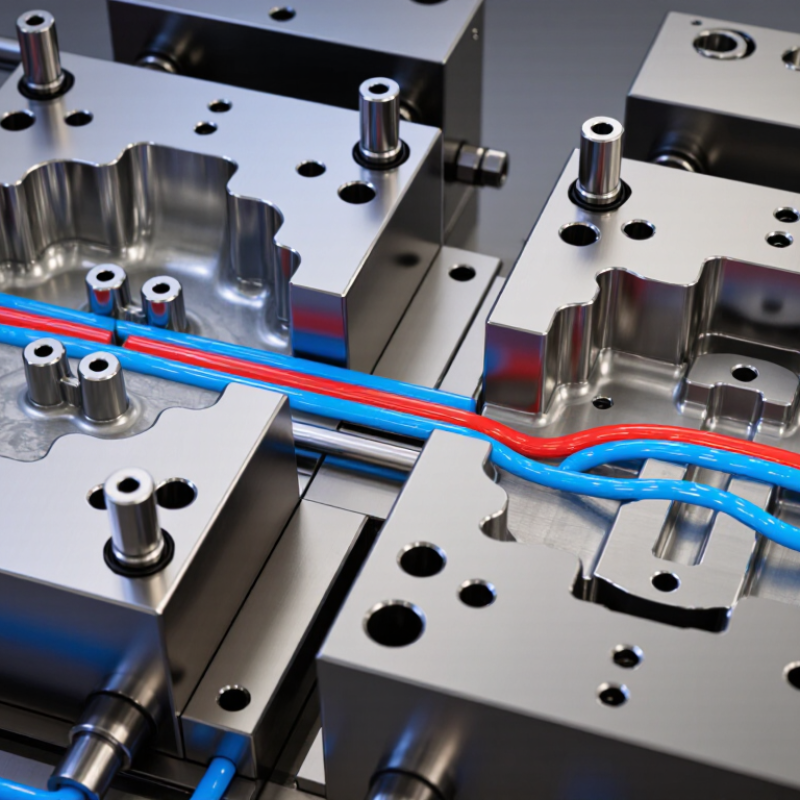
Cooling deserves careful attention. Society of Plastics Engineers injection-molding references commonly place cooling at roughly 70–80% of cycle time, though the share varies with part geometry and material. Keep channels close to the cavity and evenly spaced where practical. Avoid sharp bends and thin passages that restrict flow. Check coolant temperature and flow; a cold inlet alone does not guarantee uniform cooling. Warpage can still appear at the far end of a long channel, so simulation needs physical trials.
Tips: Use a simple channel layout first. Measure part temperature at several points after ejection. If the readings differ, revise spacing or flow before changing the whole mold. Small adjustments often help.
Plan Venting, Ejection, and Mold Structure
Good mold design starts with a clear path for trapped air. As plastic fills the cavity, air pushed toward the last-filled areas can cause burn marks or short shots. Place vents near those areas, often at the parting line or rib ends. Vent depth depends on the resin and process, so use material guidance and confirm it with trial shots. Too deep can flash.
Plan ejection around the part’s stiffness and shrink pattern. Position ejector pins beneath ribs, bosses, or other strong areas, and distribute them to reduce tilting. Keep pin marks away from visible surfaces when possible. For broad, thin parts, a stripper plate can spread force more evenly, though it adds cost and maintenance. Watch for drag marks. They can reveal uneven release.
The mold structure must support the cavity and keep its halves aligned under clamp force. Check leader pins, support pillars, and plate thickness against the mold size and expected pressure. Leave access for vent cleaning and component replacement; cramped layouts make routine work harder. A tidy CAD layout can still hide a trapped-air pocket, so review fill patterns and inspect early samples. Some choices may need revision.
Validate the Mold Design Through Simulation and Review
Before steel is cut, validate the mold design with simulation and a disciplined review. Import the final part geometry, assign the intended resin, and check wall thickness, draft, gates, runners, and cooling channels. Run filling and packing studies to locate hesitation, weld lines, air traps, and likely sink marks. Compare pressure, clamp-force, and cycle-time estimates with the available press and production target. Watch the cooling map. Uneven temperatures can warp a part after ejection, even when filling looks balanced. Simulation depends on accurate inputs; it is not a guarantee.
Review the results with the mold designer, process engineer, and product team. Trace each concern to a specific feature, such as a thin rib, a long flow path, or a cooling line close to a cavity wall. Check that vents have room to release air and that slides, lifters, and ejector pins have practical clearance. Then revise the design and rerun the key studies. A tidy color plot can still miss real shop-floor variation. Resin data, machine settings, and surface conditions may differ from the model. Record those assumptions, flag unresolved risks, and decide which details need a physical trial before production approval.