7 Injection Moulding Process Tips for Global Buyers?

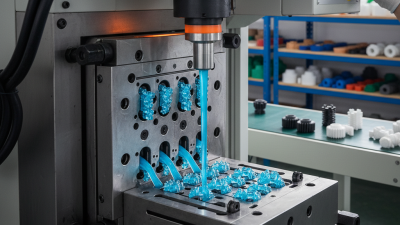
Buying molded parts across borders involves more than comparing unit prices. The real decision begins with understanding the injection moulding process behind every quotation, sample, and inspection report.

John Bozzelli, a respected scientific molding expert, explains it clearly: “The process is the product.” His point matters to global buyers. A polished sample may hide unstable fill pressure, uneven cooling, or poorly dried resin. Ask how the supplier controls mold temperature, material moisture, cycle time, and part weight. Request process data, not only attractive photographs.

Small details often reveal larger risks. Check whether critical dimensions have realistic tolerances. Confirm steel grades, cavity balance, gate location, and expected mold life. Review first-article results with actual measurement records. A supplier should also explain how it handles color variation, warpage, flash, and packaging damage during long transport.

No checklist catches everything. Even experienced teams can approve a sample too quickly. One overlooked rib, sharp corner, or weak ejector mark may create trouble after production starts. That is why buyers should compare trial results, communicate design changes clearly, and define acceptance criteria before placing an order.

These seven tips focus on practical control points. They help purchasing teams judge technical capability, reduce avoidable rework, and build more reliable supplier relationships. The goal is not simply a lower quote. It is predictable quality from the first molded part to the final shipment.
7 Injection Moulding Process Tips for Global Buyers?

Define Global Requirements with ISO 20457 Tolerances and ASTM D638 Tests

Global injection moulding projects need more than a nominal dimension. ISO 20457 defines tolerance classes for moulded plastic parts, helping buyers set realistic limits for length, flatness, and wall features. A 0.1 mm requirement may look precise, but it can become unstable after cooling, material shrinkage, and tool wear. State the tolerance class, datum references, inspection temperature, and measurement method on every drawing. Keep critical dimensions separate from cosmetic features.

ASTM D638 adds evidence about material performance. Tensile strength, elongation, and modulus can expose differences between resin batches or processing conditions. The OECD Global Plastics Outlook reports that 353 million tonnes of plastic waste were generated in 2019, with only 9% recycled. This highlights the need to document recycled content and verify its mechanical effect. Ask for test specimens, conditioning details, and batch traceability. Small details matter. A supplier may pass a tensile test while the finished part still warps during assembly. That gap is easy to miss. It is also why buyers should compare test data with actual part inspection, not rely on certificates alone. ISO 20457 tolerances and ASTM D638 results create a stronger common language, though neither standard removes every moulding risk.

Select Materials by Melt Flow, Compliance, and 0.1–2% Shrinkage

Global buyers should treat melt flow, compliance, and shrinkage as linked purchasing controls. PlasticsEurope reported 413.8 million tonnes of global plastics production in 2023. That scale increases pressure for repeatable molding data.

Tip one: request melt flow rate measured under ASTM D1238 conditions.

Tip two: match MFR with the supplier’s actual molding temperature and load. A higher MFR may fill thin walls faster, but it can reduce strength.

Tip three: approve a tested MFR range, not one attractive number.

Tip four: ask for lot-specific data, moisture limits, and drying instructions. Small differences can create visible flow marks. I have seen “equivalent” grades behave differently after drying. That assumption needs challenge.

Tip five: collect declarations for restricted substances and food-contact use where relevant. Check current requirements, such as REACH and RoHS, with qualified compliance staff.

Tip six: measure shrinkage in both flow and transverse directions. A practical design window is often 0.1–2%, but geometry, glass fiber, gate location, cooling, and packing can shift it.

Tip seven: validate dimensions using pilot molds, not only supplier datasheets. Record cavity temperature, packing pressure, cooling time, and measurement location. The PlasticsEurope 2024 industry data also shows why material traceability matters across a large, complex supply chain. Documents help. Molding evidence decides.

Design Parts with 1–2° Draft, Uniform Walls, and Moldable Ribs

7 Injection Moulding Process Tips for Global Buyers

A reliable part starts before steel is cut. The OECD Global Plastics Outlook reports that global plastic production reached 460 million tonnes in 2019. That scale makes design waste expensive. Specify 1–2° draft on vertical faces, measured from the pull direction. Polished surfaces may need more draft. Textured surfaces usually need more. Check the real texture early.

Keep wall thickness as uniform as possible. Sudden changes can create sink marks, warpage, or uneven cooling. A practical target is often 1.5–3 millimetres, depending on the resin and part size. Use ribs instead of thick solid sections. Keep rib thickness near 40–60% of the adjoining wall. Limit rib height to about three times its thickness. Add small fillets at the rib base. Sharp corners create stress and complicate filling.

Keep it moldable. The 1° rule is not magic. Large parts, deep textures, and difficult ejection may need more draft. UNEP’s Turning off the Tap report states that plastic pollution could be reduced by 80% by 2040 through system changes, including better product design. Less scrap helps, but design decisions still need testing. Request a mold-flow review, confirm ejection points, and inspect first-article samples across cavities. I have seen “uniform” walls fail after cooling because bosses and ribs were ignored. Recheck those details.

7 Injection Moulding Process Tips for Global Buyers — Design Parts with 1–2° Draft, Uniform Walls, and Moldable Ribs
No. Design Dimension Practical Starting Guideline Manufacturing Benefit Global Buyer Checkpoint
1 Draft angle Use 1–2° per side on most textured or straight-pull surfaces. For smooth polished surfaces, approximately 0.5–1° may be workable; deeper textures generally require more draft. Reduces ejection force, scuffing, drag marks, and the risk of parts sticking in the mould. Confirm draft by surface finish and texture depth. Identify any zero-draft faces, undercuts, or surfaces that may require slides or lifters.
2 Uniform wall thickness Keep nominal walls as consistent as practical. For many general-purpose thermoplastics, a typical starting range is 1.5–3.0 mm; final values depend on resin, flow length, and part size. More uniform cooling helps limit sink marks, warpage, internal stress, and uneven shrinkage. Request a wall-thickness analysis for long flow paths or large panels. Avoid abrupt changes; use gradual transitions or a transition zone.
3 Ribs and gussets Set rib thickness at roughly 40–60% of the adjoining wall. Use a rib height-to-thickness ratio near or below 3:1 where possible, with a small root radius. Adds stiffness with less material while reducing the likelihood of sink marks on the opposite cosmetic surface. Avoid thick rib intersections and dense rib networks. Check whether the rib layout can be filled without excessive injection pressure.
4 Bosses and fastening features Use a boss wall near 40–60% of the surrounding wall. Support tall bosses with ribs or connect them to nearby walls; avoid isolated thick sections. Improves filling and cooling, reducing sink, voids, cracking, and distortion around screw or insert locations. Specify the fastening method early: self-tapping screw, heat-staked insert, press-fit insert, or machine screw. Validate pull-out and torque requirements.
5 Corners and transitions Add internal radii instead of sharp corners. A common starting point is an internal radius of at least 0.5 × wall thickness, increased where stress or flow conditions require it. Reduces stress concentration, improves polymer flow, and lowers the chance of brittle failure or visible flow lines. Mark cosmetic surfaces and load-bearing corners separately. Confirm that radii are compatible with the cutter, electrode, and mould insert design.
6 Shrinkage and tolerances Use the selected resin supplier’s shrinkage data for initial mould compensation. For many standard moulded features, a general tolerance around ±0.1 mm per 25 mm is a planning reference, not a universal guarantee. Sets realistic expectations for mould dimensions, fit, assembly, and dimensional inspection. Separate critical, functional, and non-critical dimensions. State the resin grade, conditioning state, measurement method, and temperature for inspection.
7 Gate, venting, and flow direction Place gates to support balanced filling and pack critical areas. Provide adequate venting near end-of-fill regions; a commonly used vent land is about 0.5–1.0 mm, subject to resin and tool design. Helps prevent short shots, burn marks, weld-line weakness, trapped air, and inconsistent surface appearance. Ask for a mould-flow review when the part has long flow paths, multiple gates, thin walls, weld-line-sensitive areas, or fibre-filled resin.
Planning note: These values are general design starting points for thermoplastic injection moulding. Final recommendations should be confirmed against the selected resin, part geometry, surface finish, mould construction, filling analysis, and required performance.

Control Filling, Pressure, and Cooling for 30–60-Second Cycles

7 Injection Moulding Process Tips for Global Buyers?

A stable 30–60-second cycle begins with controlled filling. Tip 1: Match injection speed to part thickness, not machine habit. Fast filling can trap air, burn edges, or create weld lines. Tip 2: Check melt temperature at the nozzle and mold entrance. A displayed setting is not always the real temperature. Tip 3: Use balanced gates and runners. Uneven flow often creates different shrinkage across the same part.

Pressure needs careful adjustment. Tip 4: Set holding pressure high enough to pack the cavity, but avoid excessive stress. A part may look perfect after ejection and warp several hours later. Tip 5: Confirm the transfer point from filling to packing with actual data. Guessing from machine sound is unreliable. I have seen experienced operators miss this detail during rushed trials.

Cooling usually controls the cycle length. Tip 6: Measure cooling time from the thickest wall, not the average wall. Tip 7: Inspect water temperature, flow, and blocked channels before increasing cooling time. More seconds cannot repair poor circulation. A simple temperature map can reveal hot spots near ribs, bosses, and corners. Keep records for each material lot and mold trial. However, records are only useful when operators enter honest measurements, including failed settings.

Qualify Suppliers through FAI, SPC, and a Cpk Target of 1.33+

For global buyers, supplier qualification should begin with evidence, not polished samples. In supplier audits, I review the First Article Inspection (FAI) report against the latest drawing revision. I check dimensions, material certificates, surface finish, and measurement methods. One missing tolerance can create weeks of avoidable discussion.

FAI confirms that the initial part matches the approved design. SPC shows whether production remains stable after approval. Ask for control charts covering critical dimensions, such as a 0.02 mm wall thickness or a snap-fit width. The supplier should define sampling frequency, control limits, and reaction steps. Stop, adjust, and document.

For important characteristics, a Cpk target of 1.33 or higher is a practical qualification benchmark. However, one attractive report proves little. Request data from several production runs, not only one setup. Confirm the gauge is calibrated and the operator follows the same inspection method. A capable process can still drift after tool maintenance. That is the uncomfortable part.

Buyers should also compare Ppk during early production. Cpk reflects within-run variation, while Ppk reveals broader performance over time. If results fall below 1.33, investigate mold wear, material moisture, cooling balance, or measurement error. Do not accept unexplained “adjustments.” A clear corrective record builds trust. Perfect paperwork is not perfection. The process must repeatedly produce usable parts.

NEW JERSEY

Location

Union Tool & Mold is a mold making, repair and plastic injection molding company located in central New Jersey.
(973) 763-6611

220 Rutgers St, Maplewood, NJ 07040
ACCREDITED

Certified Company


SOCIAL PROFILE

Let’s Connect

We invite you to engage with us on LinkedIn, where you can stay updated on our latest news, insights, and professional opportunities.