Industrial systems move digital signals through cabinets crowded with variable-frequency drives, contactors, and long cable runs. A sensor may report a pressure change in milliseconds, yet a ground-potential difference can distort that signal before the controller receives it. Noise rarely announces itself. It appears as a false input, an unexplained reset, or a machine that stops between shifts. A Digital Signal Isolator transfers logic data across an electrical barrier, helping interrupt ground loops and limit fault energy reaching sensitive control electronics. Its protection has boundaries: working voltage, surge rating, data rate, and circuit layout all matter.
The business impact of interruption is substantial. Siemens’ 2024 True Cost of Downtime report estimates that unplanned downtime costs large industrial companies about 11% of annual revenue. That figure is not a direct measure of isolation failures; it shows why dependable signal paths deserve design attention. IEC 61000-4-4 also defines immunity testing for fast electrical transients, a useful reference when evaluating equipment exposed to switching disturbances. In practice, engineers should compare an isolator’s ratings with the actual transient environment, then verify creepage, clearance, and grounding on the finished board. A part number alone cannot fix poor wiring. Nor does isolation replace sound protection design. Used thoughtfully, it can help keep a noisy motor cabinet from turning a small electrical disturbance into a costly control fault.
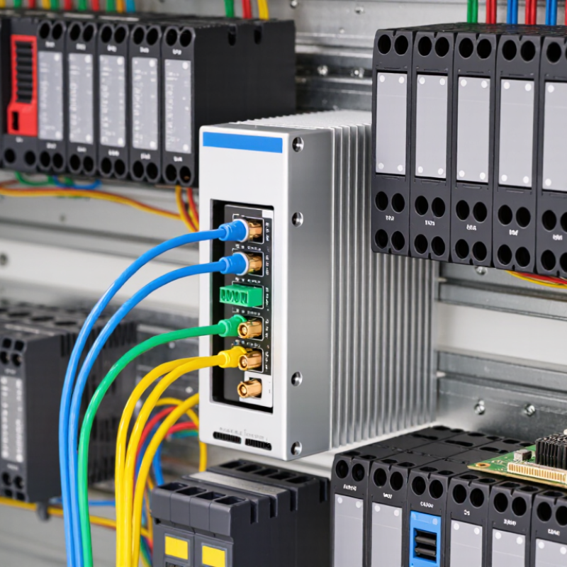
A digital signal isolator transfers logic signals between two circuits while preventing a direct electrical connection. It creates a galvanic isolation barrier, commonly using capacitive or magnetic coupling. A controller can therefore communicate with a sensor even when their ground potentials differ. The barrier also helps limit fault currents and reduce noise transfer. Isolation is not magic. The device must still match the signal speed, working voltage, and insulation requirements of the application.
Picture a motor drive switching beside a temperature sensor. Fast voltage changes can disturb the sensor’s low-level output or stress the controller input. An isolator helps separate these circuit domains, but wiring and grounding still matter.
IEC 61000-4-5 specifies Level 3 surge test values of 1 kV line-to-line and 2 kV line-to-earth for applicable ports. These are test benchmarks, not universal installation limits; requirements depend on port type and equipment class.
Check the isolator’s working-voltage and surge ratings against the system design. A rating mismatch is easy to miss.

A digital signal isolator transfers information across an electrical barrier without joining two circuits through a conductive path. On the input side, its circuitry reads a logic state, such as a high or low voltage. It encodes that change as an electric or magnetic field across tiny internal structures. No metal bridge crosses the barrier.
On the output side, a receiver detects the field and rebuilds a corresponding logic level. For a stream of bits, this process repeats, preserving the sequence and, within the device’s limits, its timing. Some designs use capacitive coupling; others use magnetic coupling. The method affects speed, noise behavior, and power use. Check the data sheet rather than assuming all isolators perform alike.
In an industrial controller, a sensor cable may run near a motor drive and carry noisy signal edges. An isolator can help prevent disturbances from directly reaching a processor while passing status pulses onward. It is not a cure for poor wiring. Grounding, placement, and rated working voltage still matter. Small details count. A missed pulse or slow edge can trouble a system, and isolation alone will not fix it.
In a plant, a sensor cable may run beside a motor drive, while its controller sits on a different power feed. Their ground potentials can differ, pushing unwanted current through the signal path. The result may be a drifting reading, a false alarm, or a damaged input. Galvanic isolation breaks that direct conductive path while passing the signal. It can reduce ground-loop current and help limit the transfer of common-mode disturbances. That is a real failure mode. Isolation is not a cure-all: it does not replace correct grounding, shielding, or surge protection.
The stakes are visible in broader reliability data. A 2024 downtime report covering 500 large companies estimated $1.4 trillion in annual unplanned losses, about 11% of revenue. That figure is not an isolation-only estimate; it shows why small signal faults deserve attention. In practice, check working voltage, transient rating, insulation spacing, and signal bandwidth against the installation. A device may block noise yet distort a fast sensor pulse if its bandwidth is too low. Commissioning matters. Record ground-potential differences and inspect readings with motors switching on and off. The measurements can reveal problems a wiring diagram misses.
Digital signal isolators create an electrical barrier between field wiring and controllers, while still transferring the signal. In a plant, a motor drive may inject switching noise into a sensor cable. Isolation helps prevent ground-loop currents and transient disturbances from reaching a PLC, data-acquisition unit, or communication interface. The result can be steadier measurements and fewer unexplained trips. Small barrier. Big difference.
The benefit matters because downtime is costly. The 2024 True Cost of Downtime report estimated that unplanned downtime costs the world’s 500 largest companies about 11% of annual revenue, or roughly $1.4 trillion. This figure does not measure isolator performance; it shows why protecting control signals deserves attention. In practice, an isolator can also reduce fault propagation between field devices and sensitive electronics, making troubleshooting less disruptive.
Selection still requires care. Check signal type, isolation voltage, bandwidth, common-mode transient immunity, and operating temperature against the application. A poorly matched device may distort fast pulses or add unwanted delay. That trade-off deserves a bench test. Isolation is not a replacement for grounding, shielding, surge protection, or safety-rated barriers where required. Engineers should verify the complete signal path under realistic switching and load conditions, rather than assume isolation alone will solve every noise problem.
Engineers should begin with the signal, not the isolator’s headline voltage rating. Check whether the interface carries SPI, UART, or another digital protocol, then match its data rate and channel direction. Measure first. A fast isolator can still cause trouble if its timing does not fit the controller or cable length. Confirm the required working voltage, transient conditions, and safety spacing against the equipment design and applicable standards.
Application details matter just as much. Compare common-mode transient immunity, propagation delay, and temperature range with conditions measured at the installation site. A motor drive cabinet, for example, may expose control wiring to sharp switching edges and heat. Check the isolator’s power needs, too; an isolated output may require a separate supply. Review the full datasheet, including test conditions, rather than treating one specification as a guarantee. Datasheets cannot fully describe a noisy cabinet.
Layout can make or break the result. Keep isolation barriers clear on the circuit board, route noisy switching nodes away from sensitive inputs, and follow the specified creepage and clearance distances. Then test. Verify signals at startup and under load, using an oscilloscope where timing or noise is uncertain. One practical detail is easy to miss: a clean bench result may not predict behavior beside a running inverter. Recheck the installation there.
