Choosing the right Exothermic Welding Powder begins with the connection, not the price per cartridge. Conductor material, size, mold design, and required connection geometry all affect the weld. A copper-to-copper joint in a dry substation differs from a copper-to-steel bond buried in damp soil. Small mismatch, poor fit. The result may look sound while still requiring closer inspection.
Reliable selection should draw on qualified engineering references, not supplier claims alone. IEEE Std 837-2014 addresses qualification of permanent connections used in substation grounding, while UL 467 covers grounding and bonding equipment. These documents help define performance expectations, but they do not replace the product maker’s instructions or project-specific review. Industry market reports can describe demand and product trends; they cannot confirm that a particular powder charge suits a specific mold and conductor combination. That distinction matters.
Before choosing a charge, verify the conductor metals, cross-sections, mold identification, and connection type against the manufacturer’s current selection chart. Check packaging condition and storage guidance, too. Moisture or damaged packaging can undermine consistency. For critical grounding networks, request documented test results and confirm that the specified connection has been qualified for its intended use. Not every catalog listing is equally clear. I would pause if compatibility details are missing, rather than infer them from a product photo. The sections below explain how to compare powder specifications, application requirements, and supplier evidence, so the final choice is technically defensible and practical in the field.
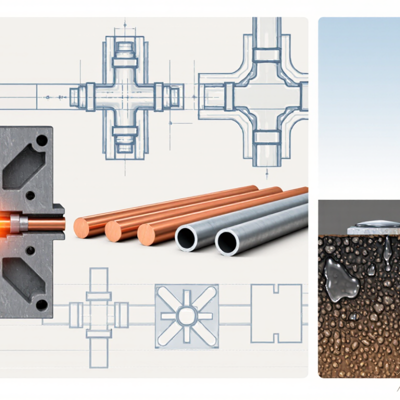
Choosing exothermic welding powder starts with identifying both metals in the connection. Copper-to-copper, copper-to-steel, and copper-to-ground-rod joints may require different powder formulations. A similar appearance does not mean the metals are interchangeable. Check the material specification, not just the surface color.
Conductor material and size matter too. Note whether the conductor is solid or stranded, its cross-sectional area, and the shape of the joint. A thick cable and a small grounding lead do not heat or fit the same way. Aluminum needs particular care because its oxide layer affects bonding; use only a process specifically approved for that combination. Details matter.
Before selecting a charge, compare the metals and conductor dimensions with the powder and mold instructions. Confirm that the mold fits the conductor securely and that contact surfaces are clean and dry. Even a little contamination can weaken the connection. If the metal grade is uncertain, pause and verify it with the project specification or a qualified technician. Guessing can seem faster, but it is a poor basis for a permanent electrical joint.

How to use this chart: Identify every metal in the connection, including conductor cores, steel components, and coatings such as zinc. These approximate melting points provide material context, not powder-selection instructions or welding temperatures. Select a powder specifically rated for the metal combination and conductor type, and follow its manufacturer’s instructions.
Match the Powder Charge to the Mold Code and Conductor Cross-Section
Choose the charge specified for the exact mold code and conductor combination. Do not select powder by cable diameter or appearance alone. A mold’s code identifies its connection design and charge requirements. Check the mold label and the powder container before each weld. Small details matter.
IEC 60228 lists nominal conductor cross-sections, including 50 mm² and 70 mm². These are conductor areas, not outside diameters. A stranded conductor’s measured diameter can vary with construction, so verify its marked size and material. IEEE Std 837-2014 covers qualification of permanent grounding connections; it reinforces why connection design and performance should be verified, not guessed. Follow the applicable mold and powder instructions, and confirm that the listed conductor sizes match the actual conductors.
One easy mistake is treating two visually similar molds as interchangeable. They may require different charges. Check for worn cavities, residue, or a damaged identification mark; uncertainty is a reason to pause. I would still cross-check the maker’s charge chart against the mold code and conductor cross-section before lighting anything. Reference tables help, but they cannot replace the specific instructions for the joint.
Choose exothermic welding powder by matching the complete joint, not just one cable’s gauge.
A straight-through splice, a 90-degree tee, and a cable-to-rod connection need different mold cavities and charge sizes. Geometry matters. Count every conductor, including parallel runs, and confirm each conductor’s material, diameter, and strand construction against the approved mold chart.
A four-cable joint is not simply a two-cable joint with extra powder; its cavity and metal volume differ.
Connection type matters, too. IEEE Std 837-2014 evaluates grounding connections under current-cycling and short-circuit testing, so select a powder-and-mold combination qualified for the intended joint configuration. Then check the project’s fault-current duty and clearing time.
IEEE Std 80-2013 estimates tolerable shock current for a 50 kg person as 0.116/√t amperes, with t measured in seconds. This is not a powder-sizing formula, but it shows why grounding performance depends on time as well as current.
Easy to overlook.
Record the joint drawing, cable count, and selected charge before installation; a rushed field substitution can leave a sound-looking connection that does not match the tested configuration.
Copper melts at 1,084.62°C, according to the NIST Chemistry WebBook. That figure matters, but it is not a powder-selection temperature. Exothermic welding creates a brief, localized reaction; the copper conductor, mold, and connection geometry all affect heat transfer. Choose a charge specified for the conductor size and mold, rather than assuming a hotter reaction automatically makes a stronger joint. Small detail, big consequence.
For copper-to-copper joints, check the powder maker’s application chart and the mold condition. A damp mold can cause steam and spatter; worn cavities can leave gaps around the conductor. ASTM B193 defines the resistivity test for electrical conductor materials, a useful reminder that joint quality involves electrical performance, not just visible fusion. I would still treat a shiny bead cautiously: appearance alone cannot confirm low resistance or mechanical integrity.
IEEE Std 837 addresses qualification of permanent connections used in substation grounding. Use its qualification framework alongside the applicable installation instructions, and inspect the cooled joint for cracks, voids, and incomplete fill. Copper’s melting point is a reference, not a recipe. The awkward part is that field conditions vary, so powder selection deserves a check against the actual cable, mold, and connection design.
A powder charge should be chosen for the conductor metal, strand size, mold, and joint geometry—not just its package label. Then verify performance against IEEE Std 837-2014, which covers qualification of permanent grounding connections. Review test records for electrical resistance, current cycling, mechanical strength, and corrosion exposure. A bright, smooth weld is useful to inspect. It is not proof of qualification.
Compare the report with the manufacturer’s data for the exact powder charge and connection configuration. ASTM B3 specifies annealed copper wire with at least 100% IACS conductivity; the IACS reference value is 58 MS/m at 20°C. That gives a useful conductor benchmark, but it does not set an acceptable weld-resistance limit. Check the test method, conductor size, and temperature correction before comparing results. Small details matter. A result from a different mold or cable construction may not represent your installation. I would also check that the records identify the tested materials and sample count; paperwork can look complete while leaving gaps. IEEE 837 applies to permanent grounding connections, so confirm that its qualification scope fits the actual joint.
| Selection dimension | What to verify in product data | Why it matters | Practical selection check |
|---|---|---|---|
| Conductor material and type | Confirm the listed application for the conductor material and form, such as copper cable, copper-clad steel, or a specified grounding component. | Different materials and conductor constructions may require different connection designs and welding procedures. | Select only a powder-and-mold combination whose published application covers the actual materials being joined. |
| Conductor size and connection geometry | Check the applicable conductor sizes, connection configuration, mold identification, and specified powder charge for that configuration. | Charge size is associated with the mold and joint design; an incorrect combination can produce an unsuitable connection. | Match the charge to the manufacturer’s application chart. Do not estimate a charge from conductor size alone. |
| Connection function and installation environment | Identify whether the joint is for grounding or bonding, and review any stated service conditions or limitations. | The connection must suit its electrical, mechanical, and environmental duties in the installation. | Use a connection design supported for the intended application and installation conditions. |
| IEEE 837 qualification evidence | Review documentation identifying the tested connection types and applicable IEEE 837 edition, along with test reports or qualification records where available. | IEEE 837 addresses qualification of permanent connections used in grounding systems; qualification is tied to the connection and its tested configuration. | Verify that the evidence covers the proposed joint configuration. Do not treat a powder’s general description as proof that every connection is qualified. |
| Electrical and mechanical performance | Check published test results or qualification data relevant to current-carrying performance, connection integrity, and the specified service requirements. | A sound selection depends on verified performance of the completed joint, not on powder quantity or appearance alone. | Compare documented results with the project specification and applicable qualification requirements. |
| Mold and tooling compatibility | Confirm that the powder charge is specified for the mold type, mold condition, and connection configuration being used. | The mold forms and contains the reaction material; compatibility is essential to producing the intended joint geometry. | Follow the documented mold-and-charge pairing and inspection or replacement instructions. |
| Storage, shelf life, and handling | Check packaging condition, lot traceability, stated shelf life, storage limits, and handling precautions on the product documentation and safety data sheet. | Moisture, damaged packaging, or unsuitable storage can affect handling and process reliability; reactive materials also require safe handling. | Use in-date, intact material stored as directed, and follow the safety data sheet and site procedures. |
| Installation instructions and quality control | Review instructions for conductor preparation, mold setup, ignition, cooling, inspection, and any required operator training or records. | Preparation and process control influence the consistency and quality of the finished connection. | Choose a documented process that installers can follow and that supports project inspection and traceability requirements. |
Selection note: Verify the current IEEE 837 edition and project requirements, and obtain application-specific qualification and installation data from the powder and connection-system supplier.
