What Is an Automatic Transfer Switch and How Does It Work?

When utility power fails, a building’s lights may go dark before anyone reaches the generator. An Automatic Transfer Switch (ATS) helps close that gap. It monitors the normal supply and, when voltage fails or moves outside set limits, transfers connected loads to a backup source. When utility power returns and stabilizes, the switch can transfer them back.

The need is measurable. The U.S. Energy Information Administration’s Electric Power Annual reported an average of 5.6 hours of electricity interruptions per U.S. customer in 2022, including major events. That figure does not describe every site, but it shows why continuity planning matters. An ATS does not generate electricity. It coordinates the changeover, using electrical and mechanical interlocks to prevent the two sources from being connected improperly.

Mike Holt is a recognized electrical educator. I cannot verify a verbatim ATS quotation from him, so the following is a paraphrase, not a direct quote: “A transfer switch must isolate sources and connect the load safely.” That distinction matters. A switch’s rating, sensing settings, transfer delay, and installation all affect how it performs. NFPA 110 also sets requirements for emergency and standby power systems, including transfer equipment. The standard is a reference, not a substitute for project-specific engineering.

The basic idea is simple. The details are not. A short interruption may be acceptable for one load, but costly for another. Understanding the ATS sequence helps readers ask better questions about backup-power design, maintenance, and testing.
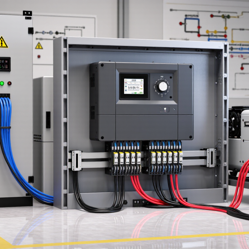
What Is an Automatic Transfer Switch and How Does It Work?

What an Automatic Transfer Switch Is

An automatic transfer switch (ATS) is electrical equipment that moves a building’s load between a normal power source and an alternate source. In a common setup, that means utility power and a standby generator. The ATS monitors supply conditions, such as voltage and frequency. If utility power fails or becomes unacceptable, it can signal the generator to start, then connect the load when generator power is stable. When utility power returns, the switch transfers back, often after a delay. The generator may then cool down before stopping. Not magic. Just carefully timed switching.

The switch is not the generator, and it does not create electricity. Its job is to coordinate the connection safely and reliably. This distinction matters in real settings: a brief transfer interruption can affect sensitive equipment, while poor maintenance can leave a switch unable to operate when needed.

The U.S. Energy Information Administration reported that customers experienced an average of 5.5 hours of power interruptions in 2022, including major events (EIA, Electric Power Annual).

Uptime Institute’s 2024 outage analysis found that 54% of surveyed organizations said their most recent significant outage cost more than $100,000.

Those figures do not measure ATS performance, but they show why continuity planning deserves attention. The switch’s rating, installation, and periodic inspection should match the loads it serves; that part is easy to underestimate.

Key Components and Their Functions

An automatic transfer switch (ATS) connects a building to a preferred power source and shifts the load to a backup source when needed. Its sensing circuit monitors voltage and, in many systems, frequency. If utility power falls outside set limits, a control module decides whether the outage is long enough to trigger a transfer. A brief dip may not be enough. Settings matter.

The switching mechanism moves electrical contacts between the two sources. In an open-transition switch, one source disconnects before the other connects, creating a short interruption. Interlocking prevents both sources from feeding the load at once. Some systems use closed-transition switching, which briefly overlaps sources under controlled conditions. That design requires compatible equipment and careful setup. The enclosure protects internal parts from dust, impact, and accidental contact, but its rating must suit the installation environment.

After detecting a fault, the controller can signal a generator to start, then transfer the load once its output stabilizes. When utility power returns, the ATS may wait before switching back, helping avoid a response to unstable power. It can also allow the generator to cool down afterward. These delays are adjustable, and poor settings can cause nuisance transfers. Inspection should include contact condition, control wiring, and test results; a switch can appear normal while a worn contact is heating under load.

What Is an Automatic Transfer Switch and How Does It Work? - Key Components and Their Functions

Component or Stage What It Does How It Works in the Transfer Process
Source connections Provide connections for the normal power source and the alternate source, commonly utility power and a generator. The switch selects one source at a time to supply the connected load, subject to its design and configuration.
Voltage and frequency sensing Monitors electrical conditions on the preferred source and, when configured, the alternate source. If the preferred source falls outside configured limits, the controller can initiate a transfer sequence. Specific monitored conditions depend on the equipment.
Controller and logic Processes source status, programmed settings, and transfer signals. After detecting an unacceptable normal source, it can signal a standby generator to start and transfer the load when the alternate source is suitable.
Time-delay settings Apply programmed delays to help avoid unnecessary switching due to brief disturbances and to allow a generator to stabilize. Depending on the settings, delays may be used before starting a generator, transferring to the alternate source, or retransfer to the normal source.
Switching contacts Make and break the electrical connection between the selected source and the load. The contacts move between source positions using the transfer mechanism. Contact ratings must be appropriate for the system and load.
Transfer mechanism and interlocking Moves the contacts and helps prevent incompatible source connections. Many designs use a break-before-make sequence, disconnecting one source before connecting the other. Some systems use different transfer methods where designed for the application.
Neutral switching (if fitted) Switches the neutral conductor along with the phase conductors in configurations that require it. Whether the neutral is switched depends on the system grounding arrangement, applicable electrical requirements, and switch design.
Load terminals and enclosure Connect the switched output to the load and house the electrical and control components. The enclosure provides protection appropriate to the installation environment; the load receives power from whichever source is selected.
Typical return-to-normal sequence Restores the load to the normal source after it returns and remains acceptable for the configured period. The controller retransfers the load, often after a programmed delay, and may keep the generator running briefly for cooldown before signaling it to stop.

Transfer sequences, delays, and neutral arrangements vary by switch design and installation.

How the Switch Detects a Power Failure

An automatic transfer switch (ATS) monitors the incoming utility supply through voltage-sensing circuits. It does not wait for a room to go dark. Instead, it checks whether voltage—and, in many systems, frequency—stays within acceptable limits. Some installations monitor each phase, since one weak phase can trouble three-phase equipment. That detail matters.

When readings fall outside preset limits, the controller usually confirms the fault for a brief period. This delay helps prevent switching during a momentary dip, such as when a large motor starts nearby. If the outage persists, the ATS can signal a standby generator to start. The switch typically waits until the generator’s output is stable before connecting it to the building’s circuits.

Settings vary with the equipment and site conditions. A threshold that is too sensitive can cause needless transfers; one that is too tolerant may prolong exposure to poor power. There is no universal setting that suits every installation. During commissioning, a qualified technician can verify sensing, timing, and transfer behavior under controlled conditions. A quick look at the display can help, but it cannot replace measured checks.

How Power Transfers Between Sources

An automatic transfer switch (ATS) monitors the utility supply and connects a building to a backup source when power fails. It checks voltage and frequency against preset limits. If the readings fall outside those limits, the ATS signals a generator to start. Once the generator’s output is stable, the switch moves the load from utility power to generator power.

That pause matters.

With open-transition switching, the utility connection breaks before the generator connection closes, creating a brief interruption. Closed-transition equipment can overlap sources briefly, but only when the system is designed for it. When utility power returns and remains stable, the ATS transfers the load back, then allows the generator to cool down.

NFPA 110’s Type 10 classification describes emergency power systems designed to supply power within 10 seconds; actual performance depends on the complete installation. Uptime Institute’s 2024 outage analysis found that 54% of respondents said their most recent significant outage cost more than $100,000. An ATS cannot prevent every outage, but a tested transfer sequence can reduce disruption.

Tips: Test the switch under load according to the manufacturer’s instructions, and inspect connections and generator starting batteries. Record transfer times. A setting that seems minor can matter; I’d verify it rather than assume it’s correct.

Common Types and Applications of Automatic Transfer Switches

Automatic transfer switches (ATS) vary by how they move a load between normal and backup power. An open-transition unit disconnects the utility before connecting a generator, creating a brief interruption. It is common. This arrangement suits many homes and small shops, where a short pause is acceptable. Closed-transition equipment briefly overlaps sources, but only when voltage, frequency, and phase are properly synchronized. It can reduce interruptions for sensitive processes, but requires more controls and careful commissioning. Delayed-transition designs pause between sources to let motors or residual voltage settle. Selection is not a label-only decision.

Applications shape the choice. Residential systems often use open-transition ATS equipment with standby generators to keep lights, refrigerators, and heating controls running. Offices may protect elevators, network rooms, and essential lighting. Hospitals and data centers may need carefully engineered systems with redundant sources. Industrial sites can use ATS equipment for pumps, ventilation, or production lines, though not every machine should restart automatically. Some loads need sequencing or manual inspection. An experienced electrician checks load size, generator startup time, fault ratings, and maintenance access before specifying equipment. Even a well-chosen switch cannot compensate for an undersized generator. That detail is easy to miss.

Automatic Transfer Switches: How Common Types Transfer Power

An automatic transfer switch (ATS) monitors a primary power source and switches a load to an alternate source when needed. The chart compares how many sources may be connected to the load at once during each transfer method.

How to read it: Open-transition switches disconnect one source before connecting the other. Delayed-transition switches add a deliberate interval between disconnection and reconnection. Closed-transition switches briefly connect both sources during transfer, but only when system conditions allow. Values show the maximum number of sources connected at once—not transfer time.

Common applications: ATS equipment is used with standby generators or alternate utility feeds to supply loads in places such as hospitals, data centers, commercial buildings, and industrial facilities. The appropriate transfer method depends on the load, power sources, and system design.

NEW JERSEY

Location

Union Tool & Mold is a mold making, repair and plastic injection molding company located in central New Jersey.
(973) 763-6611

220 Rutgers St, Maplewood, NJ 07040
ACCREDITED

Certified Company


SOCIAL PROFILE

Let’s Connect

We invite you to engage with us on LinkedIn, where you can stay updated on our latest news, insights, and professional opportunities.